Powerflow Drag Conveyors
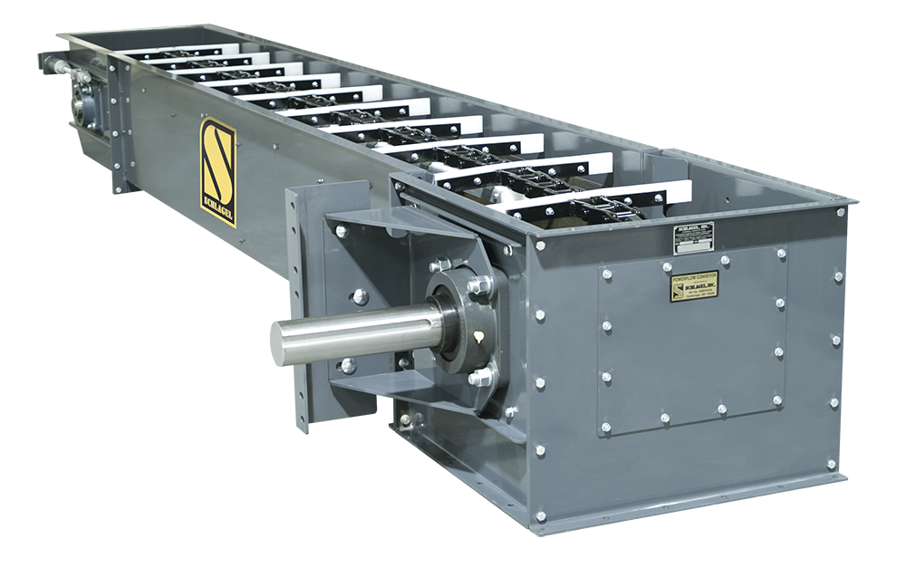
The PowerFlow Conveyor introduced an affordable concept of “en-masse” conveying to the grain industry in 1970. Since then it has become an attractive alternative to other commercial methods of conveying because of its ability to deliver high volumes of material using a minimum amount of space. Many years of experience and continued improvement in reliability and efficiency allow the PowerFlow Conveyor to set the standards for our marketplace.

Conveying Speeds
In general, the maximum recommended chain speed is 180 FPM. Total conveyor life increases rapidly as this speed is reduced. Severe duty service conveyors should be limited to approximately 120 FPM or less.
Capacities
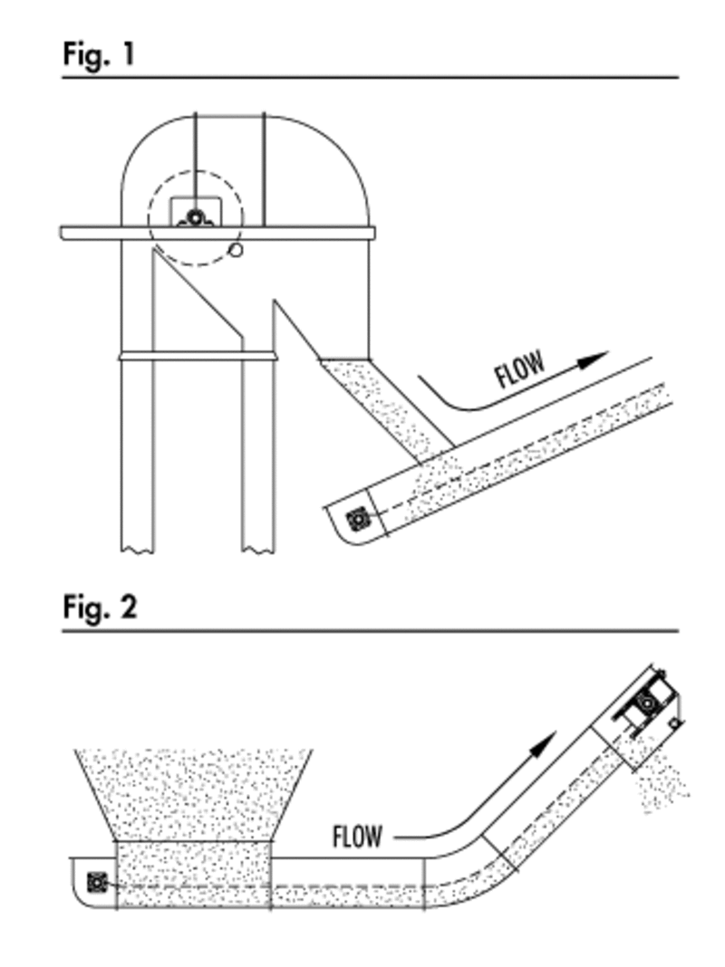
When flood feeding (see Figure 2) the capacity is exactly that of the design tables shown here. In this condition the conveyor is 100% full and capacity is adjusted by regulating the conveyor speed.
When the input is controlled (see Figure 1) the conveyor should be run at 105% of the maximum capacity that can be input. This will assure enough capacity within the conveyor housing to eliminate the possibility of material backup or plugging.

Maximum Lengths
The maximum length of a Powerflow Conveyor is limited by the pull required on the conveying chain. This is a function of the material weight per foot of conveyor, the friction factor of the material, breaking load of the chain, safety factors and chain wear. Acceptable chain life is often the most important factor.
The figures shown in Table 1, see page 101, serve as guidelines for maximum lengths. The shorter value shown is for the higher friction and or weight material such as soybean. The longer value can be used with materials like corn or wheat. It is possible to increase these lengths if chain speed or service requirements are reduced.
Inclines
Material flowability determines the maximum incline at which a conveyor may be operated. When the incline exceeds 4 degrees (7/8 inch rise per foot of run) chain modifications may have to be considered. These modifications can increase the inclinability to 9 degrees or more.
Inlets
Inlets usually consist of a simple housing above the conveyor. Care must be taken to keep the inlet well in front of the tail sprocket. Long hoppered inlets from dump pits etc., will consume additional horsepower. Factory engineering is available to help you with this special hopper design and horsepower requirement.
If you intend to feed the conveyor from more than one inlet at a time, then you must make certain that the conveyor is not running full after the last inlet. Consult the factory for further information on this.
Drives
Most installations use shaft mounted drives because of their reliability and efficiency. Gear and roller chain drives may be used but access to the head section cover and a rigid mechanical connection between the head and drive platform must be provided. We can furnish drives of any configuration to suit your installation.
Example RequirementsA conveyor 160 feet long to convey 14,000 BPH of soybean and corn is required. It is to be fed from a 14,000 BPH leg and it will be placed on an incline with the discharge end 7 feet higher than the inlet.
Conveyor Size
Referring to Table 1, page 101, it is found that Model 1618 is the smallest conveyor that will handle 14,000 BPH. Because soybean will be conveyed, the shorter value listed under “Maximum Length” (153 feet) must be used. Since 160 feet is required, Model 1620 will be selected as all of the parameters fall within the requirements set forth in our example.
Check Incline
Within the discharge elevated 7 feet above the inlet, it will be necessary to check the incline to see if it exceeds the 4 degree maximum angle or 7/8 inch rise per foot of run. This can be accomplished by multiplying the elevation (7 feet) by 12 and dividing by the overall length (160 feet) The answer is (.53 inches “rise per foot of run” is well below the maximum incline. If the angle had been greater than 4 degrees, a chain modification may have been necessary. In that case the factory should be contacted for assistance.


| Name | Type | Size |
|---|---|---|
| Installation & Operation Manual | manual | 3.25MB |